English
 français
 Español
 русский
 português
 العربية
 tiếng việt
 Türkçe
 ไทย
ไทย Indonesia
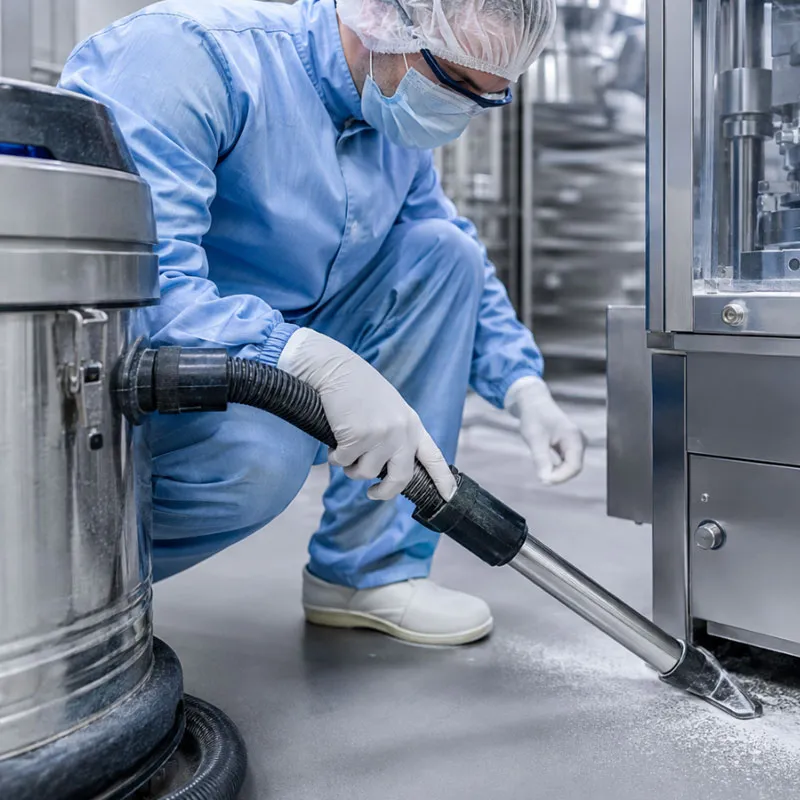
Pharmaceutical production demands a different standard of industrial cleaning. The objective is not only to remove visible residue but also to manage fine powder, support housekeeping discipline, redu...
Read More
An industrial central vacuum system should be designed from the material, pickup task, simultaneous users, pipe route, vertical lift, filter loading, disposal method, hazardous-area requirements, and future expansion. The main unit is selected only after the required airflow and pressure losses are estimated for the worst credible operating path. A successful system captures material reliably at each outlet, maintains conveying velocity, protects filters, and allows operators to empty waste without creating a new exposure or dust-release problem.
A central vacuum project is not simply a large vacuum connected to long pipe. It is a coordinated material-recovery network. The vacuum producer, separator, filters, valves, piping, branches, hoses, pickup tools, electrical controls, discharge equipment, and exhaust location must operate as one system. An error in any part can reduce suction at the farthest point, overload the filter, clog the pipe, waste energy, or make the system difficult to use.
Waidr Vacuum Cleaner (Shanghai) Co., Ltd. supplies industrial vacuum equipment for portable cleaning, process integration, dust control, and centralized recovery. The company’s central solutions are used in demanding environments such as automotive manufacturing, pharmaceuticals, semiconductors, chemicals, tobacco, food processing, power generation, coal and coke handling, cement, and steel production. This guide gives engineers and procurement teams a practical framework for defining a project before requesting a final design.
An industrial central vacuum system is a fixed network in which one or more vacuum producers create negative pressure through permanent piping so material can be collected from multiple remote pickup points and conveyed to a central separator, filter, and waste receiver.
The system may serve routine floor cleaning, overhead dust removal, machinery cleanup, process spill recovery, direct source capture, or production-line integration. Some projects have only a few outlets used one at a time. Others include many branches, automatic valves, multiple users, pre-separators, continuous discharge, explosion protection, or redundant vacuum producers.
The architecture can improve housekeeping because operators connect a lightweight hose at a nearby inlet rather than transporting a heavy portable machine around the plant. It can also place the primary collector and exhaust away from sensitive production areas. However, those advantages depend on correct pipe sizing, sufficient vacuum at the most demanding outlet, good valve discipline, and a collection method that matches the material.
Waidr’s industrial central vacuum system page provides a commercial starting point for large facilities. A project quotation should then be developed from site drawings and application data rather than from building area alone.
An industrial central vacuum system typically uses relatively high vacuum and lower airflow through smaller piping for material pickup and housekeeping, while a dust collection system typically uses higher airflow and lower static pressure through larger ducts to capture airborne contaminants near their source.
The terms are often mixed in marketing, but the engineering duty is different. A central vacuum network may recover settled dust, granules, chips, powders, fibers, liquids, or process debris through hoses and tools. A local exhaust ventilation or dust collection system captures contaminants as they are generated, before they disperse into the workplace. Some factories need both.
| Design Factor | Industrial Central Vacuum System | Dust Collection / Local Exhaust System | Typical Procurement Question |
|---|---|---|---|
| Primary purpose | Housekeeping, spill recovery, machine cleanup, material transfer | Capture airborne contaminants at or near the emission source | Is the material already settled, or must it be captured while generated? |
| Pressure characteristic | Higher vacuum to overcome hose, tool, lift, and smaller-pipe resistance | Lower static pressure with larger airflow volumes | What is the longest and most restrictive operating path? |
| Piping | Often smaller diameter, designed for material conveying and branch outlets | Often larger ducting connected to hoods and enclosures | What particle size and conveying velocity must be maintained? |
| User interaction | Operators connect hoses or activate dedicated pickup points | Runs with the process or ventilation demand | How many users or machines operate simultaneously? |
| Collected material | Settled dust, chips, granules, fibers, liquids, mixed debris | Airborne dust, fumes, mist, or process emissions | Is the material abrasive, combustible, toxic, wet, sticky, or hot? |
| Control strategy | Valves, hose inlets, vacuum demand controls, automatic discharge | Dampers, hoods, fans, make-up air, process interlocks | Should the system respond to active outlets or run continuously? |
OSHA defines local exhaust ventilation as a system that captures and removes emitted contaminants before they dilute into workplace air. Therefore, a housekeeping central vacuum should not be represented as a replacement for source-capture ventilation when the process requires LEV. Waidr also provides a separate dust collection system category for projects whose primary task is airborne dust capture and control.
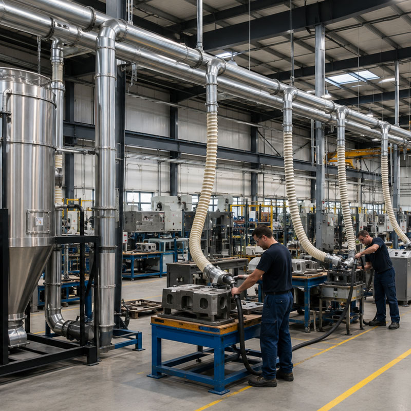
Material definition is the process of documenting the physical, chemical, safety, and handling properties that determine how debris will enter, move through, separate from, and leave the vacuum system.
The project team should list every expected material rather than naming only the main product. A machining plant may collect metal chips, grinding dust, coolant, oil, fasteners, and floor debris. A food plant may collect flour, sugar, ingredients, packaging fragments, and washdown liquid. A textile plant may collect lint, long fibers, thread, and dust. These mixtures behave differently in a pipe and separator.
Document:
Material name and process source.
Particle-size range and largest expected object.
Bulk density and approximate collection rate.
Dry, wet, oily, sticky, fibrous, abrasive, corrosive, or cohesive behavior.
Normal and maximum credible temperature.
Combustibility, toxicity, reactivity, and area classification.
Whether different materials may mix inside the same receiver.
Required containment and disposal method.
Next, define the task at each pickup point. Floor cleaning with a 50 mm tool, machine-bed chip recovery, narrow-nozzle powder cleaning, overhead beam vacuuming, and direct connection to a production machine have different airflow and vacuum requirements. A single design value cannot represent every tool unless the system is sized from the worst credible combination.
Pickup-point mapping identifies where material enters the network, how operators use each outlet, and which combinations can operate at the same time.
Create a scaled layout showing the vacuum room, main header, branches, vertical risers, hose stations, process connections, separators, collector, exhaust, access doors, and discharge area. For each pickup point, record the tool diameter, hose length, frequency, expected collection rate, and duty duration.
Simultaneous-use assumptions have a major influence on capital cost and energy consumption. Designing all outlets to operate at once may greatly oversize the system. Designing for one user when three production teams routinely clean at shift change will create poor performance. Use actual operating schedules and include a reasonable future allowance.
| Pickup Point | Task | Hose / Tool | Expected Use | Material Load | Can Operate With |
|---|---|---|---|---|---|
| Grinding cell A | Fine dust and small metal debris | 40 mm hose, floor and crevice tools | 15 minutes per shift | Moderate fine dust | Grinding cell B |
| CNC line | Chips and residual coolant | 50 mm oil-resistant hose | Intermittent during changeover | Dense chips and liquid | One housekeeping outlet |
| Packaging mezzanine | Light powder on ledges | 38 mm long hose | Weekly overhead cleaning | Low-density powder | No other long-hose outlet |
| Bulk bag station | Spill recovery | 50 mm pickup wand | Unplanned peak event | High short-term load | Priority mode only |
Control logic can limit simultaneous use through valve interlocks, priority modes, or operator procedures. Demand control may allow the vacuum producer to reduce speed when fewer outlets are open, but the minimum conveying conditions must still be maintained.
Pipeline design determines the diameter, route, branch geometry, materials, supports, and cleanout provisions required to convey collected material without excessive pressure loss, blockage, wear, or static accumulation.
The shortest route is not always the best route. Pipe should be accessible for inspection, avoid unnecessary bends, protect building movement joints, and prevent low points where liquids or dense material can settle. Branches should merge in the direction of flow. Sharp tees, abrupt expansions, flexible-hose sections, and repeated tight elbows add resistance and can create wear points.
Key pipeline inputs include:
Design airflow at each active inlet.
Required conveying velocity for the material.
Longest equivalent pipe length.
Vertical lift and downward sections.
Number and type of bends, branches, reducers, and valves.
Pipe internal roughness and material compatibility.
Expected erosion from abrasive dust or chips.
Static-control and bonding requirements.
Liquid drainage, cleanouts, and blockage access.
Pipe diameter affects both velocity and pressure loss. A pipe that is too small creates high resistance and may limit airflow. A pipe that is too large can allow velocity to fall below the level needed to keep material moving. The correct diameter is therefore not simply “bigger is better.” The engineer should calculate each operating scenario and confirm performance at the farthest or most restrictive path.
Where liquid recovery is required, the network should be reviewed for pooling, slope, drainage, and separation. A dry powder system should not be casually converted to liquid recovery. Likewise, long fibrous material can bridge in branches or around internal obstructions and may need larger inlets, special separators, or a different transport strategy.
Airflow and vacuum-pressure calculation establishes the operating point the vacuum producer must deliver after losses through tools, hoses, pipe, separators, filters, silencers, and discharge equipment are included.
The design begins at the pickup point. Determine the airflow needed for the tool and material, then calculate pressure loss along the selected path. Add losses from straight pipe, bends, branches, valves, hose, nozzle, separator, clean filter, expected loaded filter, and exhaust components. The vacuum producer should be selected from its performance curve at the required operating point, not from free-air airflow or maximum sealed vacuum alone.
Free-air airflow is measured with minimal restriction. Maximum vacuum is measured near zero airflow. Neither condition represents normal operation. The real system operates between those endpoints. A quotation should show the expected airflow at the design pressure, the assumed number of active outlets, and the condition of the filter used in the calculation.
Useful design scenarios include:
Nearest outlet with one user.
Farthest outlet with one user.
Design number of simultaneous users at typical branches.
Worst credible combination of long hose, vertical lift, and loaded filter.
Future expansion condition.
Blocked or closed-inlet protection condition.
The system should include protection against operating outside the vacuum producer’s safe range. Pressure-relief valves, bypass airflow, motor protection, phase monitoring, temperature monitoring, or variable-speed control may be appropriate depending on the equipment. Instrumentation should allow maintenance teams to identify rising filter resistance or abnormal vacuum before performance becomes unacceptable.
Separation and filtration remove collected material from the air stream while protecting the vacuum producer, controlling emissions, and allowing safe disposal.
A pre-separator can remove large chips, dense granules, liquids, sparks, or heavy dust before the main filter. Cyclonic separation can reduce filter loading, but efficiency depends on particle size, density, airflow, geometry, and operating conditions. It should not be treated as a universal substitute for final filtration.
The filter system should be selected from particle size, toxicity, combustibility, moisture, stickiness, loading rate, cleaning method, and required discharge quality. NIOSH defines HEPA filtration as at least 99.97 percent efficient at capturing 0.3 micrometer particles under its stated definition. In an industrial vacuum installation, total containment also depends on filter seals, housing integrity, bypass control, installation, and maintenance.
Compare:
Primary filter type and total filter area.
Pre-separation efficiency and receiver capacity.
Manual shaking, reverse-air, pulse-jet, or automatic filter cleaning.
Cleaning-air quality and compressed-air demand.
Filter differential-pressure monitoring.
Safe filter-change and bagging procedure.
Secondary or HEPA filtration requirements.
Exhaust return or discharge location.
Pulse cleaning can support high dust loads, but compressed-air pressure, pulse duration, valve condition, and filter compatibility must be maintained. Wet, sticky, or oily material may not release from a dry filter effectively. In those cases, separation or collection architecture should change rather than relying on more frequent pulsing.
Receiver sizing determines how long the system can operate between disposal events and whether waste can be removed safely without excessive manual handling or production interruption.
Calculate volume from the collection rate and bulk density, then apply a practical fill limit. A 100-liter receiver does not safely hold 100 liters of every material during operation. Filters, cyclone discharge, internal geometry, and dust expansion reduce usable capacity. Dense material may reach a safe weight limit before the container appears full.
Common discharge options include removable bins, drums, liners, endless bags, rotary valves, double-dump valves, screw conveyors, tipping containers, and pneumatic transfer. The choice depends on containment, continuity, material flow, hazardous-area requirements, and destination.
Ask:
How many kilograms are collected per hour or shift?
Can the operator safely move the filled container?
Must the process continue during emptying?
Does the waste need a sealed liner or closed transfer?
Could the material bridge, compact, smear, or react in the receiver?
Is dust release during bag change acceptable?
Will forklifts, pallet jacks, hoists, or drum lifters be available?
Waste handling is frequently underestimated. A powerful system that captures dust efficiently but releases it during emptying does not provide a complete control solution.
Hazardous-area design integrates the material hazard, classified location, ignition control, explosion protection, bonding, grounding, isolation, and safe discharge into the complete central vacuum network.
The project may require the vacuum producer and collector to be located outside the classified process area, but that alone does not eliminate risk. Dust-laden pipe can carry hazardous material across boundaries. The design should consider conductive continuity, static accumulation, spark or hot-particle entry, filter location, explosion venting or suppression where required, isolation devices, exhaust, and safe access for maintenance.
Combustible-dust projects should be reviewed by competent safety and engineering professionals using the applicable local standards and the facility’s dust hazard analysis. The exact protection strategy depends on the material test data and architecture. Do not state that a central system “guarantees OSHA or EPA compliance.” Equipment can support a compliant program, but compliance belongs to the complete facility design, operation, maintenance, and documentation.
For large airborne-dust loads, an industrial dust collector or dedicated local exhaust system may be required in addition to central housekeeping vacuum outlets. The project team should clearly separate process capture from cleanup duty.
Controls and instrumentation coordinate vacuum demand, protect equipment, indicate filter condition, and help operators identify faults before collection performance is lost.
A basic system may use manual start/stop control and relief protection. A larger network may include variable-frequency drives, valve position feedback, pressure transmitters, filter differential-pressure sensors, bin-level sensors, automatic discharge, pulse-cleaning control, alarm history, remote monitoring, and production-line interlocks.
Define how the system responds when:
No outlets are open.
One outlet opens suddenly.
The maximum allowed number of outlets operates.
A filter reaches the warning differential pressure.
A receiver reaches high level.
A discharge valve fails.
A branch becomes blocked.
A motor overheats or loses phase.
Plant power or compressed air is interrupted.
Critical processes may justify duty/standby vacuum producers or parallel filters so maintenance can occur without stopping production. Redundancy should be based on downtime cost and safety consequence, not added automatically. The operating team must understand how equipment switches over and how the isolated unit is made safe for maintenance.
Layout selection determines where the main equipment is installed and how the network balances pipe length, access, noise, exhaust, waste logistics, and hazardous-area separation.
| Layout | Advantages | Limitations | Suitable Situation |
|---|---|---|---|
| Central equipment room | Consolidated maintenance, noise separation, controlled exhaust and waste area | Longer pipe runs and possible building modifications | Large plant with many distributed outlets |
| Outdoor skid | Moves noise, heat, and some dust-handling activities outside production space | Weather protection, freeze risk, corrosion, zoning, and access must be addressed | Facilities with suitable external service area |
| Multiple local central systems | Shorter pipe, easier material segregation, independent production zones | More equipment sets and maintenance points | Large campus or incompatible materials |
| Mobile high-vacuum unit with temporary manifold | Lower initial infrastructure and flexible deployment | Less convenient than permanent outlets; setup and hose management required | Shutdown cleaning, construction phases, or changing layouts |
| Process-integrated stationary vacuum | Dedicated performance and direct machine interlock | Limited flexibility and may require separate housekeeping system | Continuous production-line extraction or transfer |
Noise and heat should be included in the layout decision. A motor room may need ventilation and acoustic treatment. Exhaust should not be routed to an occupied or sensitive area without review. Maintenance space should allow filter removal, motor access, receiver handling, and safe lifting.
Quotation comparison is the process of checking whether suppliers have used the same design assumptions, operating point, scope, documentation, and acceptance criteria.
A low-cost quotation may assume one user, a clean filter, short pipe, no controls, and manual waste emptying. A higher quotation may include simultaneous use, loaded-filter performance, automatic discharge, hazardous-area components, commissioning, and training. The prices are not comparable until scope differences are normalized.
Require each proposal to state:
Design materials and collection rates.
Number of simultaneous pickup points.
Required airflow and pressure at each design condition.
Vacuum producer performance curve or operating point.
Pipe diameters, approximate lengths, and included fittings.
Separator and filter type, area, and cleaning method.
Receiver capacity and discharge arrangement.
Controls, instruments, alarms, and communication interface.
Hazardous-area and combustible-dust assumptions.
Noise level and exhaust arrangement.
Electrical load, compressed-air demand, and utility conditions.
Installation, commissioning, testing, training, warranty, and spare parts.
Include acceptance testing. The test can measure vacuum and airflow at specified outlets, simultaneous-use performance, filter differential pressure, control response, receiver discharge, alarms, noise, and visible leakage. Define the test method before the purchase order so all parties understand what constitutes successful delivery.
Lifecycle cost is the combined cost of equipment, installation, electricity, compressed air, filters, bags, maintenance labor, waste handling, downtime, and future modification over the expected service period.
Oversizing increases capital and energy cost. Undersizing reduces productivity and encourages operators to use compressed air or sweeping, which can create exposure and housekeeping problems. Variable-speed control can reduce energy when demand varies, but the system must maintain adequate conveying velocity and stable equipment operation.
Filter pressure loss affects energy. A poorly selected or overloaded filter makes the vacuum producer work harder while reducing pickup performance. Pre-separation, correct filter area, effective cleaning, and timely maintenance can improve system stability. Pipe leakage also wastes capacity; a commissioning and inspection program should include closed valves, seals, flexible connectors, and unused branches.
Productivity benefits may include shorter cleanup time, fewer portable-machine movements, reduced extension cables, better access to overhead areas, less production interruption, and more controlled waste handling. These benefits should be measured from actual labor and downtime data rather than assumed percentages.
A complete design checklist gives Waidr’s engineering team enough information to develop a technically relevant central vacuum concept and reduces repeated clarification during quotation.
Provide a scaled plant layout in PDF or CAD format.
Mark all pickup points, elevations, and expected hose lengths.
Describe each material and attach safety data and test information.
State the collection rate at each outlet and per shift.
Identify simultaneous-use combinations and future outlets.
Provide area classification and combustible-dust requirements.
State available voltage, frequency, compressed air, and control standards.
Describe desired waste container, liner, or continuous discharge.
Identify indoor or outdoor location, ambient range, washdown, and corrosion conditions.
State noise limits, exhaust restrictions, and cleanroom or hygiene requirements.
Define communication, remote monitoring, or production-line interlocks.
List required certificates, drawings, manuals, training, and acceptance tests.
Waidr states more than 20 years of industrial vacuum experience, a 20,000 square meter production base, and service to more than 30,000 clients. These company-level capabilities can support customized projects, but the final design should still be verified against the specific site inputs and agreed acceptance criteria.
The total number of installed points can be much larger than the number used simultaneously. Capacity depends on the airflow required at each active outlet, pipe losses, hose and tool restrictions, filter condition, and vacuum-producer curve. A design should state both installed outlets and simultaneous users. Building area alone is not enough. Waidr should receive the layout and usage schedule before sizing the main unit.
There is no universal maximum length. The practical limit depends on pipe diameter, material, airflow, vertical lift, bends, branch geometry, hose length, separator loss, filter resistance, and available vacuum pressure. The longest equivalent path must be calculated. A system with 100 meters of well-designed pipe may perform better than a shorter network with undersized pipe, tight bends, leaks, and a restrictive tool.
It may be possible in a purpose-designed system, but mixed wet and dry recovery changes piping, separation, corrosion, filter, drainage, disposal, and contamination requirements. Liquids can pool in low points or damage dry filters. Reactive materials may be incompatible with water or other liquids. The supplier should review every expected material and operating sequence. Separate networks or dedicated pre-separators may be safer and easier to maintain.
No. Filter selection depends on particle size, toxicity, process sensitivity, discharge location, regulatory requirements, and containment goals. HEPA may be appropriate for fine or hazardous particles, but a central vacuum also needs suitable pre-separation, seals, housing, filter cleaning, and safe change-out. HEPA does not replace combustible-dust protection or local exhaust ventilation. The complete system and application should be evaluated.
Common causes include too many open outlets, undersized pipe, excessive hose length, sharp bends, leakage, clogged branches, a loaded filter, a full receiver, incorrect valve position, or a vacuum producer operating away from its design point. Troubleshooting should compare measured pressure and airflow with commissioning values. Randomly installing a larger motor may not solve a pipe, filter, or operating-procedure problem.
Commissioning should verify airflow and vacuum at designated outlets, performance with the specified number of simultaneous users, filter differential pressure, control and alarm response, receiver discharge, leakage, grounding where required, noise, motor protection, and operator procedures. The test conditions should include hose and tools, not only open pipe. Results should be recorded as the baseline for future maintenance and troubleshooting.
1. U.S. OSHA Technical Manual, Section III, Chapter 3, Ventilation Investigation: https://www.osha.gov/otm/section-3-health-hazards/chapter-3
2. U.S. OSHA Standard 1910.94, Ventilation: https://www.osha.gov/laws-regs/regulations/standardnumber/1910/1910.94
3. U.S. CDC/NIOSH Ventilation Frequently Asked Questions: https://www.cdc.gov/niosh/ventilation/faq/index.html
An industrial central vacuum system succeeds when the engineering begins at the pickup point and follows the material through the complete path to safe disposal. The design must define the cleaning task, simultaneous users, conveying conditions, pipe route, pressure losses, separator, filters, receiver, controls, exhaust, and hazardous-area requirements. Selecting the vacuum producer before those inputs are known creates a high risk of oversizing, low pickup performance, clogging, or excessive operating cost.
Waidr can develop portable, stationary, dust-control, and centralized solutions for industrial facilities. To receive a useful proposal, provide a scaled layout, material data, operating schedule, pickup requirements, utilities, area classification, and waste-handling expectations. A transparent design basis and measurable acceptance test will produce a more reliable system than a quotation based only on factory floor area or motor power.
.webp "Battery-powered industrial vacuum cleaner (electronic dust cleaning)")